Kit 1005 Landing Gear
4 posts
• Page 1 of 1
Kit 1005 Landing Gear
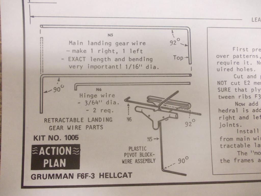
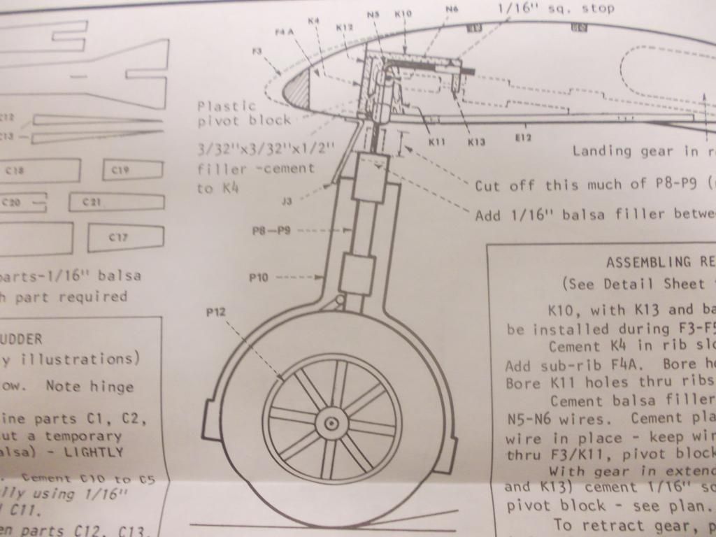
I'm struggling with the landing gear on this kit. What is confusing to me is the different views of the gear on the plans and they all seem to show the wire sitting or attached to different parts being either K4 or K10. Plus on bending the wire bottom left hand corner of the Action Plan it shows the main wire in two halves but I suspect that it should as per the pictures be in one piece. The rest of the kit has gone together really well and as being only the 2nd balsa kit I have ever built I want to make sure I have it right.
- leadshed
- Posts: 1
- Joined: Mon Dec 30, 2013 9:56 am
Re: Kit 1005 Landing Gear
I've never done a 1000 kit so I'm not much help, but I know they give options for retractables, and this may be your problem. Dont worry you'll get the right answer soon.Sorry I was'nt much help.
- davidchoate
- Posts: 1263
- Joined: Wed Aug 14, 2013 6:41 am
- Location: PHiladelphia PA
Re: Kit 1005 Landing Gear
The shape of some 3D parts, such as landing gear wire, is often depicted on model plans using two orthographic views. Imagine the part rotated 90 degrees. You will then see a front view and side (or top) view. However, it's only one part.
- David Lewis
- Posts: 289
- Joined: Thu Jun 13, 2013 11:47 am
- Location: Orlando FL
Re: Kit 1005 Landing Gear
Wow, I am impressed...Second model and you are into the 1000 series, way to go.
Let me see if I can give some advice. I have not built the kit but I have it, and just opened it up. You are referring to the K parts so I see you are building the retracts. I see your confusion and it may take me some time to figure it out also. So this gear not only folds up, it will rotate 90 degrees. This is a challenge...
First I can answer about the bottom left box "Retractable Landing Gear Wire Parts" There are 2 wires. N5 and N6. N6 is easy, one bend, so they show one view. N5 is shown in two views as there are 2 bends in different directions. The picture on the bottom right helps you visualize the parts.
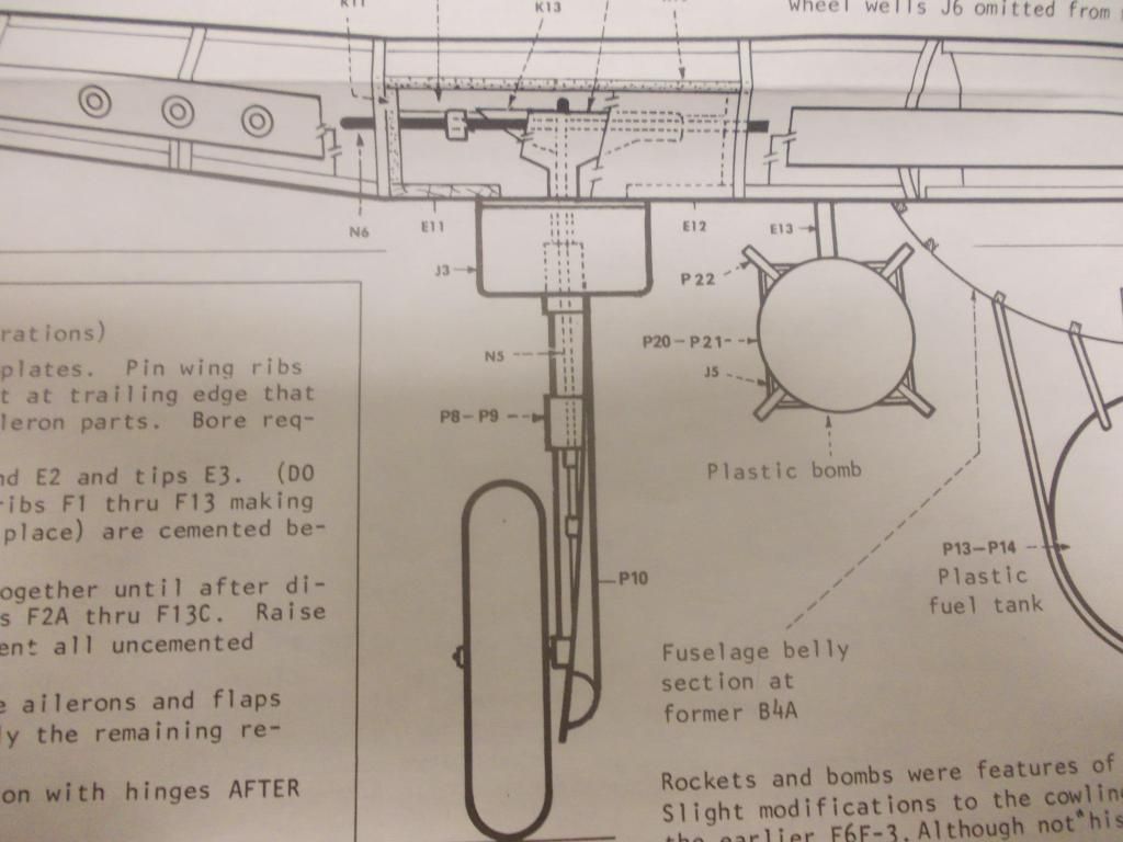
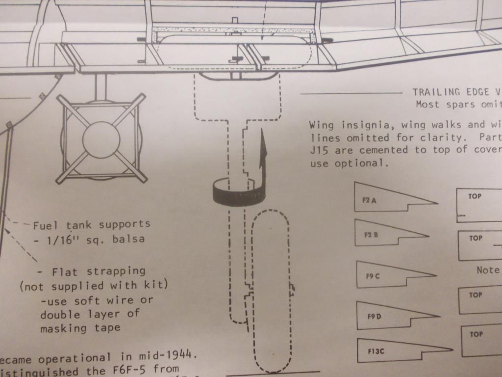
I put in a few pictures for the rest of the builders to see what we are talking about.

Wires N5 and N6

Gear Down

Gear Rotating

Side View
I will study this more myself...
 UPDATE: In the Action Plan is says see detail sheet. There is a sheet of paper in your kit 8 x 11 "Construction Details" There are detailed instructions for Retractable Landing Gear, with notes and pictures A to E. After you look that over let me know if it is clear, or if you need more help.
Mitch
Let me see if I can give some advice. I have not built the kit but I have it, and just opened it up. You are referring to the K parts so I see you are building the retracts. I see your confusion and it may take me some time to figure it out also. So this gear not only folds up, it will rotate 90 degrees. This is a challenge...
First I can answer about the bottom left box "Retractable Landing Gear Wire Parts" There are 2 wires. N5 and N6. N6 is easy, one bend, so they show one view. N5 is shown in two views as there are 2 bends in different directions. The picture on the bottom right helps you visualize the parts.
I put in a few pictures for the rest of the builders to see what we are talking about.

Wires N5 and N6

Gear Down

Gear Rotating

Side View
I will study this more myself...
Mitch
- Mitch
- Posts: 1347
- Joined: Mon Aug 22, 2011 9:16 pm
- Location: Kent, WA
4 posts
• Page 1 of 1
Return to General Building Questions
Who is online
Users browsing this forum: No registered users and 21 guests
