F4U-4 Corsair to U Control

Ask other modelers for a little help / knowledge ?

Postby ADW 123 » Sat Apr 16, 2011 3:29 pm

squish, i find that fun.

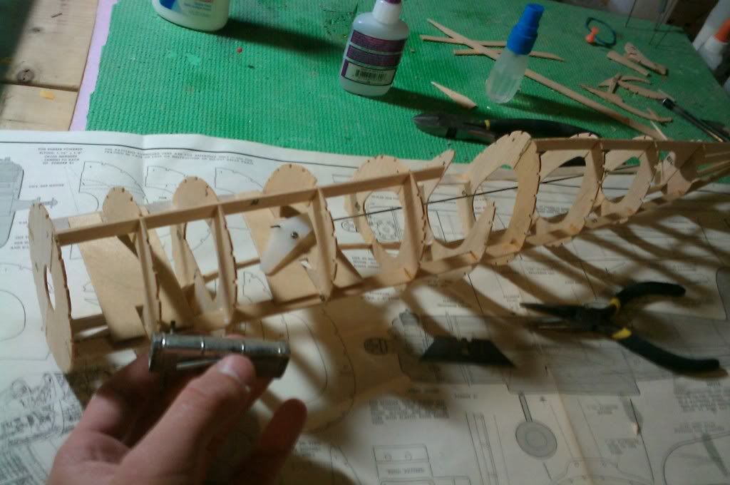
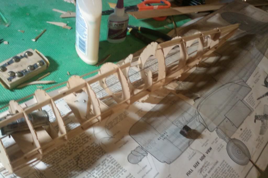
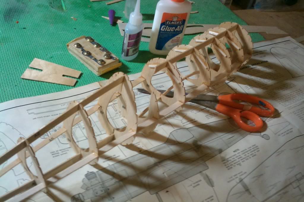
i had to add some support to the formers, because the side keel was causing problems. it caused them to bend a bit, so i added the support.

Image

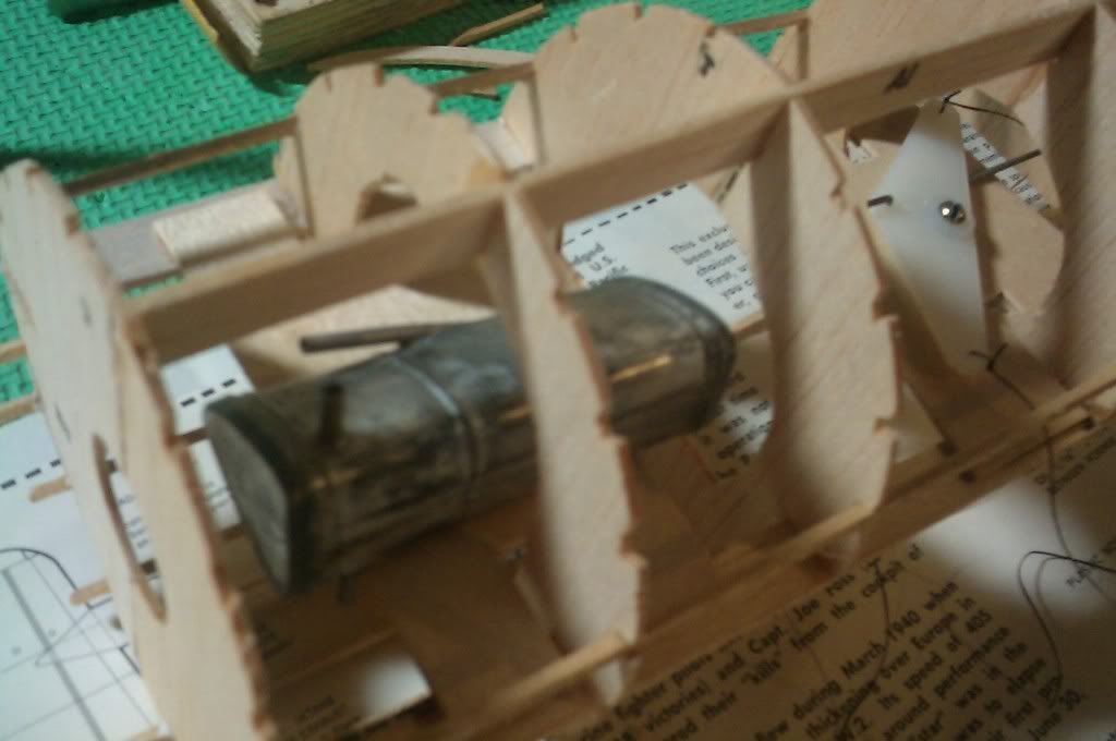
instillation of the bellcrank. that is a perfect wedge fuel tank... have to figure outt which way it goes in..

Image
ADW 123
 
Posts: 1158
Joined: Mon Feb 22, 2010 5:22 pm
Location: Cincinnati, Ohio

Postby BillParker » Sat Apr 16, 2011 4:38 pm

All critical operations, and all done in an outstanding manner.

stay with it.
William H. Parker Jr. (Bill Parker)
President, Parker Information Resources
http://www.parkerinfo.com/ap.htm bparker@parkerinfo.com
BillParker
 
Posts: 1031
Joined: Sat Jan 19, 2008 1:21 pm
Location: Houston, Texas

Postby BillParker » Sat Apr 16, 2011 4:40 pm

um... just a thought tho...

you may want to get some leadout string tied off to that bellcrank befrore you can't get at it anymore...
William H. Parker Jr. (Bill Parker)
President, Parker Information Resources
http://www.parkerinfo.com/ap.htm bparker@parkerinfo.com
BillParker
 
Posts: 1031
Joined: Sat Jan 19, 2008 1:21 pm
Location: Houston, Texas

Postby BillParker » Sat Apr 16, 2011 4:41 pm

Image
William H. Parker Jr. (Bill Parker)
President, Parker Information Resources
http://www.parkerinfo.com/ap.htm bparker@parkerinfo.com
BillParker
 
Posts: 1031
Joined: Sat Jan 19, 2008 1:21 pm
Location: Houston, Texas

Postby ADW 123 » Sat Apr 16, 2011 5:10 pm

Mr. Parker or anyone who knows-

know which way that perfect wedge tank goes in? i had some fun figureing it out a while ago, but have forggoten since then.

ill stick some string on the bell crank later. i have to find a bolt for it first. i had one... or a few... where did they go???

also, you can see the forward bit of plywood, for the fuel tank. i have since then cut some of the former out so i can fit the tank with ease. now, which way it goes in...


love this!
ADW 123
 
Posts: 1158
Joined: Mon Feb 22, 2010 5:22 pm
Location: Cincinnati, Ohio

Postby flash52 » Sat Apr 16, 2011 7:22 pm

The narrow side of the tank goes to the outside of the circle. The fuel line connects to the tank outlet on the end. This faces the motor and is the same level as the,needle valve on the motor. Higher position will tend to flood out the motor. Lower will tend to starve the motor. Use thin music wire on the bell crank for your lead outs. Then it will be easy to unclip your control lines and handle.

flash
flash52
 
Posts: 67
Joined: Tue Mar 10, 2009 5:31 pm
Location: Wichita,KS

Postby ADW 123 » Sat Apr 16, 2011 8:09 pm

ive already got nylon thread in as leadouts. ill jsut use a swivel leader that connects to the leadout, and then ill tie rapala knots onto the ends of the control line threads. this way, ill just be able to unclip them.

wait, so the angled bit on the tank should go on the outside? and it should be on the top or bottom? and i connect the main fuel line to the angled bit?
ADW 123
 
Posts: 1158
Joined: Mon Feb 22, 2010 5:22 pm
Location: Cincinnati, Ohio

Postby mr.charlse » Sun Apr 17, 2011 3:42 am

if your going to spin around in a circle a lot nylon lead outs work, but if you want to do loops or wing-overs then you will have to get steel lead outs.
i believe that Sig stocks them.
mr.charlse
 
Posts: 48
Joined: Sun Mar 13, 2011 10:41 am

Postby ADW 123 » Sun Apr 17, 2011 7:47 am

i built a fokke wulf to u control (the bigger one) last summer, and i used the nylon thread. the motor was so powerful, not only was i able to put on parts that allowed me to launch my plane solo, but i was also able to take the thing straight up over my head. those motors have got some power...
ADW 123
 
Posts: 1158
Joined: Mon Feb 22, 2010 5:22 pm
Location: Cincinnati, Ohio

Postby ADW 123 » Sun Apr 17, 2011 9:40 am

getting stringers on


Image

cant get stringers on around the tank area until i know that this is in correct. this is how i think it goes in.

Image
ADW 123
 
Posts: 1158
Joined: Mon Feb 22, 2010 5:22 pm
Location: Cincinnati, Ohio

Postby ADW 123 » Sun Apr 17, 2011 3:16 pm

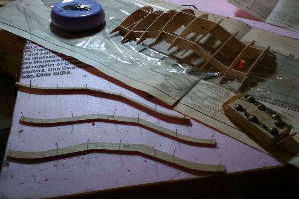
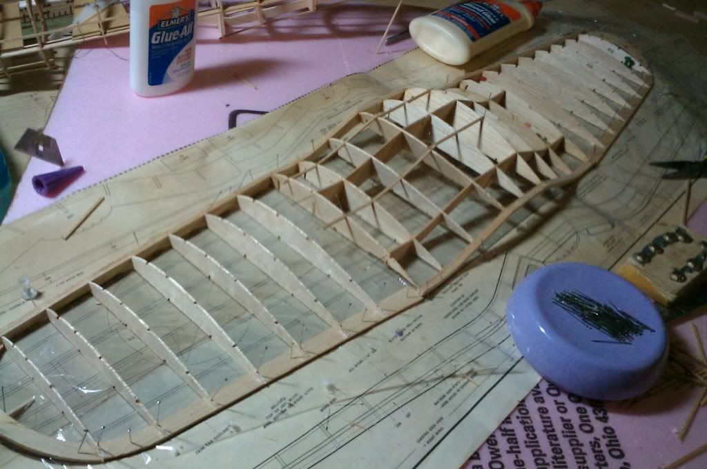
wngs started-

Image
ADW 123
 
Posts: 1158
Joined: Mon Feb 22, 2010 5:22 pm
Location: Cincinnati, Ohio

Postby BillParker » Sun Apr 17, 2011 5:52 pm

Love the inverted Gull...

Image

Image
William H. Parker Jr. (Bill Parker)
President, Parker Information Resources
http://www.parkerinfo.com/ap.htm bparker@parkerinfo.com
BillParker
 
Posts: 1031
Joined: Sat Jan 19, 2008 1:21 pm
Location: Houston, Texas

Postby ADW 123 » Sun Apr 17, 2011 7:54 pm

Image

nice huh?
ADW 123
 
Posts: 1158
Joined: Mon Feb 22, 2010 5:22 pm
Location: Cincinnati, Ohio

Postby BillParker » Sun Apr 17, 2011 8:30 pm

That is purty, ain't it?
William H. Parker Jr. (Bill Parker)
President, Parker Information Resources
http://www.parkerinfo.com/ap.htm bparker@parkerinfo.com
BillParker
 
Posts: 1031
Joined: Sat Jan 19, 2008 1:21 pm
Location: Houston, Texas

Postby ADW 123 » Sun Apr 17, 2011 8:46 pm

ill add dihedral tomorrow, and maybe finish the wing. i cant get much more done on the fuse until i know for sure on how that fuel tank goes in... soooo somebuddy let me know please!

i hope guillows has made some improvements on this kit since this one was made. i had a heck of a time with some of the wing construction. that was another reason i decided on u control for this one, and a new kit to static.
ADW 123
 
Posts: 1158
Joined: Mon Feb 22, 2010 5:22 pm
Location: Cincinnati, Ohio

PreviousNext

Return to General Building Questions

Who is online

Users browsing this forum: No registered users and 17 guests